

 Current position > Product detail
『Ge At600 Ultrasonic Flow Meter Manual PDF: Transducer Alignment, Spacing, and Terminal Block Wiring』Related information(flow rotameter|digital flow meter|balo meter|hydraulic flow meter|volumetric meter|positive displacement meter|pitot tube flow meter|displacement meter|cfm meter|variable area flow meter|inline flow meter|differential pressure flow meter|calibrated flow meter|velocity meter|paddle wheel flow meter|oval gear flow meter|anemometer hvac|multiphase flow meter|doppler flow meter|thorpe tube flowmeter|heat flow meter)
GE AT600 Ultrasonic Flow Meter: Transducer Alignment, Spacing, and Terminal Block Wiring
Quick Answer: Align the transducers parallel to the pipe axis. Enter pipe and fluid data into the GE AT600 transmitter to get the correct spacing value. Wire power, 4-20 mA output, and RS485 exactly as shown on the terminal label inside the enclosure.
Most GE AT600 ultrasonic flow meter faults start with three installation errors. The transducers are not aligned. The spacing is measured from the wrong point. The terminal block receives the wrong supply voltage. This guide follows the GE AT600 manual PDF sections on transducer alignment, spacing, and terminal block wiring.
Transducer Alignment
Alignment on clamp-on transducers controls how much ultrasonic energy reaches the second transducer. The transducer face must sit flat on the pipe surface. The transducer center line must stay parallel to the pipe center line. Use the alignment guide or clamping fixture shown in the manual PDF. Tighten the fixture in small steps on both sides. Do not tighten one side fully and then force the other side.
We have seen this on customer sites many times. A water treatment plant in Vietnam installed the GE AT600 on a DN150 carbon steel pipe. The meter showed very low signal strength. The issue was a small angle error of about 3 degrees. After realigning the transducers parallel to the pipe axis, signal strength increased from 25 to 74. That removed the unstable reading.
For wetted transducers, check the insertion depth and orientation. The transducer face must point into the flow path. Check that gaskets do not block the face. Check the thread engagement as well. Cross-threading is easy to miss on a hot pipe or a tight skid.
Transducer Spacing
Spacing is not a fixed number that you copy from one project to another. You need pipe outside diameter, wall thickness, pipe material, liner material, liner thickness, fluid type, and fluid temperature. The GE AT600 transmitter calculates spacing after you enter those values. Write down the spacing in millimeters shown on the display before marking the pipe.
Measure the spacing from the inner end of one transducer to the inner end of the other transducer. Some installers measure from the cable end. That creates a large path error. On a DN50 pipe, a 5 mm error can reduce signal quality enough to trip the fault alarm.
But do not copy a spacing value from another job. Even the same pipe size can need different spacing when the fluid or pipe material changes.
For clamp-on transducers, mark the pipe with the mounting fixture. Clean the pipe surface with a wire brush and remove loose paint or scale. Use the coupling compound supplied in the kit. Do not use general purpose grease unless the manual approves it. Air gaps between the transducer face and the pipe reduce signal. In a dairy plant in Australia, a thin layer of dried product caused intermittent signal loss every cleaning cycle. Cleaning and rechecking the spacing solved the problem.
Terminal Block Wiring
The terminal block wiring must follow the diagram inside the AT600 enclosure. Power terminals typically accept 90 to 260 V AC or 24 V DC depending on the model. Check the label before connecting. A common mistake is connecting 24 V DC to the AC input. The transmitter may not start or the internal fuse may open.
So check the terminal label before you connect. Use crimp ferrules for stranded wire. Tighten terminal s
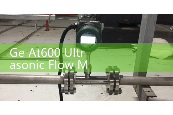
Typical connections include power input, 4-20 mA output, pulse or digital output, and RS485 Modbus RTU. Some AT600 versions also have a relay for total flow or alarm. After wiring, power the unit with the terminal cover open only for testing. Then close the cover to keep the ingress protection rating.
Here is the thing. Many electrical faults are not electronic failures. They are wrong terminal jumpers or loose neutral wires. Before sending a board for repair, measure the supply voltage at the terminal block under load. We have seen a wastewater site in the Philippines where the DC supply dropped from 24 V to 17 V when the AT600 started. The cable run was too long for the wire size.
Quick Installation Sequence
Set the transmitter on the bench first. Enter pipe data and fluid data. Install transducers. Use enough couplant. Check spacing. Wire power. Check 4-20 mA. Check RS485. Then apply flow.
How to Get Support
If you need a replacement GE AT600, a spare transducer set, or a compatible Silver Automation Instruments ultrasonic flow meter, send us your pipe size in DN or inches, pipe material, wall thickness, fluid, flow range, pressure in bar, and temperature in degrees C. For example, a DN100 carbon steel water line at 20 degrees C and 200 m3/h often works with a clamp-on ultrasonic meter with 4-20 mA HART and RS485 Modbus output. We will quote a meter with the right transducer frequency and mounting kit.
Call Silver Automation Instruments at +86-25-68650347. Use Whatsapp at +86-25-52155837 or WeChat at +86 15365082610. Visit flow-meter.com.au for product data sheets and installation guides.
Frequently Asked Questions
What is the most common GE AT600 transducer alignment error? One transducer is mounted at a small angle to the pipe axis. Even a 2 or 3 degree error can cut signal strength enough to cause a fault. Use the alignment guide and check both transducers from the side and from the top.
How do I calculate transducer spacing for a GE AT600? Enter the pipe outside diameter, wall thickness, pipe material, liner, fluid type, and fluid temperature into the AT600 transmitter. The transmitter calculates the spacing in millimeters. Measure between the inner ends of the two transducers.
Can I use 24 V DC on a GE AT600 AC input terminal? No. Check the terminal label inside the enclosure first. Connect 24 V DC only to a DC powered AT600 model. Wrong supply voltage can open the fuse or damage the power supply.
Why does my GE AT600 show low signal strength after wiring is correct? Check transducer alignment and spacing first. Then check the pipe surface condition and coupling compound. Air gaps, loose fittings, rust, or scale reduce acoustic coupling.
What terminal connections are standard on the GE AT600? The standard connections are power input, 4-20 mA output, pulse or digital output, and RS485 Modbus RTU. Some versions add a relay output for total flow or alarm. Always follow the wiring diagram inside the terminal cover.
Send us your pipe schedule, fluid temperature, and required output signal. We will help you confirm the transducer type and terminal wiring for your application.