

『Gas Flow Meter Diagram Layout: Upstream and Downstream Straight Pipe Run Rules in P&ID Layouts』Related information(flow rotameter|digital flow meter|balo meter|hydraulic flow meter|volumetric meter|positive displacement meter|pitot tube flow meter|displacement meter|cfm meter|variable area flow meter|inline flow meter|differential pressure flow meter|calibrated flow meter|velocity meter|paddle wheel flow meter|oval gear flow meter|anemometer hvac|multiphase flow meter|doppler flow meter|thorpe tube flowmeter|heat flow meter)
Gas Flow Meter Diagram Layout: Upstream and Downstream Straight Pipe Run Rules in P&ID Layouts
Quick Answer: A gas flow meter diagram layout on a P&ID must show enough upstream and downstream straight pipe run to keep the flow profile stable before the meter. For most inline gas flow meters, plan 15D upstream and 5D downstream after a single elbow. After a control valve or regulator, plan 30D upstream or install a flow conditioner. Silver Instruments supplies gas flow meters with P&ID-ready installation notes for DN15 to DN300 lines.
Most engineers skip this part on small skids. That is where gas flow meter error starts. On a P&ID, straight run notes are not optional text. They tell the piping designer where to place the meter, the flow conditioner, and the tag. Without them you get a meter installed after a partially open valve. The reading shifts. The plant engineer blames the flow meter. The real problem is the upstream pipe layout.
Why Straight Pipe Run Appears on P&ID Layouts for Gas Flow Meters
Gas flow meters need a stable velocity profile before the sensor. An elbow or a tee creates swirl. A control valve creates jetting and turbulence. That swirl and jetting cause repeatability errors, not just offset errors. On a P&ID, the straight run requirement appears next to the flow meter tag, for example FT-101. It is a design control, not a suggestion.
We have seen this on customer sites many times. A compressed air line in Vietnam had a vortex flow meter installed only 4D after a control valve. The reading shifted by 3 percent under low flow. The fix was a longer upstream run and a flow conditioner. The pipe rack had space, but the layout was not checked against the P&ID straight run rule.
Standard Straight Pipe Run Rules for Gas Flow Meter Layouts
Use these values as a baseline for P&ID development. They apply to clean gas lines and standard upstream fittings.
- 90 degree elbow before meter: 15D upstream, 5D downstream
- Two elbows in plane before meter: 20D upstream, 5D downstream
- Two elbows out of plane before meter: 30D upstream, 5D downstream
- Control valve or regulator before meter: 30D upstream, 5D downstream
- Reducer before meter: 10D to 15D upstream, 5D downstream
D means nominal pipe diameter. For a DN80 gas line, 15D equals 1200 mm of straight pipe before the meter. For a DN150 line, 30D equals 4500 mm. In tight packaged skids, a flow conditioner can reduce the upstream requirement. But the P&ID must show the flow conditioner symbol and its part number. It is not enough to write straight run on the drawing and assume the fabricator will leave room.
Gas Flow Meter Types and Their P&ID Straight Run Sensitivity
Thermal mass flow meters are less sensitive to swirl but still need 10D upstream and 5D downstream after a valve. Vortex flow meters are more sensitive. They pick up vortex shedding from upstream fittings, so follow 20D to 30D upstream rules. Coriolis mass flow meters tolerate shorter runs but still need flow conditioning for low density gas. Silver Instruments recommends thermal mass flow meters for biogas and flare gas. For compressed air and natural gas, we quote inline vortex flow meters with P&ID layout
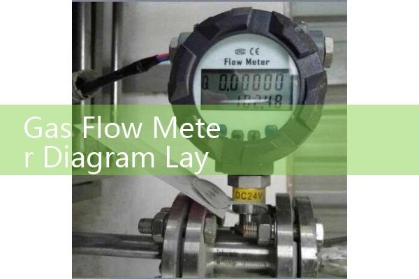
Many gas flow meters need pressure and temperature compensation. A vortex flow meter on a natural gas line gives volumetric flow. To get mass flow or standard volume, add a PT100 temperature sensor and a pressure transmitter. Show these on the P&ID near the meter. Use 4-20 mA HART signals to the flow computer or PLC. If the gas is natural gas or biogas, specify ATEX Zone 1 or Zone 2. Silver Instruments supplies Ex approved flow meters for hazardous area P&ID loops.
P&ID Symbol and Tag Placement for Gas Flow Meters
On a P&ID, place the flow meter symbol at the straight run segment. Do not place it between two elbows. Show the tag number near the symbol, for example FT-101. Add a note next to the instrument bubble: 15D upstream, 5D downstream required. This note travels from P&ID to isometric drawings. It prevents the piping fabricator from cutting the line too short.
Here is the thing. In practice, the P&ID note does not guarantee a good installation. The pipe fitter may not read the note. The site engineer may not check it. This is why we send a simple installation sketch with every gas flow meter order. The sketch shows the meter, the straight runs, the flow conditioner, and the tag position. It helps the installation crew see what 15D means on their own pipe rack.
What to Send Us for a Gas Flow Meter P&ID Layout
Send us your gas type, pressure in bar, temperature in °C, pipe size DN, and flow range in kg/h or Nm3/h. Also send a simple P&ID sketch if you have one. We will return a gas flow meter model, straight pipe run recommendation, and tag notes. If you are unsure about the upstream fitting type, send a photo of the pipe rack. That works too.
Contact Silver Automation Instruments by Tel: +86-25-68650347 or WhatsApp: +86-25-52155837. WeChat: +86 15365082610. We serve industrial customers in Southeast Asia, Oceania, Latin America, Africa, and the Middle East.
FAQ: Gas Flow Meter Straight Pipe Run Rules
What is the minimum upstream straight pipe run for a gas flow meter?
For a standard inline gas flow meter after a single elbow, use 15D upstream. After a control valve, use 30D upstream. D is the pipe diameter. Confirm with the flow meter supplier because some meters need less.
Does downstream straight pipe run matter for gas flow meters?
Yes. Most gas flow meters need 5D downstream. This reduces flow disturbance after the meter. It helps thermal, vortex, and Coriolis meters hold calibration.
Can I install a gas flow meter after a control valve?
Yes, but allow 30D upstream or install a flow conditioner. Gas flow after a control valve contains strong turbulence. A flow conditioner can reduce the upstream requirement in tight skids.
What pipe size range does Silver Instruments cover for gas flow meters?
We quote gas flow meters from DN15 to DN300. Larger sizes are available on request. We need your pipe size and flow range to select the correct meter bore.
Do you provide P&ID layout support for gas flow meters?
Yes. Send us your P&ID sketch or line data. Silver Automation Instruments can provide straight run notes, tag placement, and installation drawings for gas flow meter projects.
 Hot Product
 Related AD